Determination of Positioning Datum in T25-1701316 Gear Machining
The determination of positioning datum in gear machining is a critical step to ensure gear accuracy (e.g., tooth profile, tooth alignment, and pitch cumulative error), directly influencing gear meshing performance, transmission smoothness, and service life. The selection of positioning datum must adhere to principles such as "datum unity," "datum coincidence," and "mutual datum," while integrating gear structure, machining processes, and equipment capabilities for comprehensive design. Below is a detailed analysis:
I. Basic Principles of Positioning Datum Selection
Principle of Datum Unity
In multi-process machining, the same set of positioning datums should be used as much as possible to minimize datum conversion errors. For example, hobbing, shaving, and grinding processes all use the gear's inner bore and end face as positioning datums.
Principle of Datum Coincidence
The positioning datum should coincide with the design datum (e.g., the gear's pitch circle or axis) to avoid datum misalignment errors. For instance, when the gear's inner bore axis serves as the design datum, the inner bore must be used as the positioning datum during machining.
Principle of Mutual Datum
For high-precision surfaces (e.g., tooth flanks), mutually correcting positioning methods can be employed. For example, during gear grinding, the inner bore is first positioned for rough grinding, and then the ground tooth flanks are used as the datum for precision grinding of the inner bore.
Principle of Self-Datum
The machined surface itself is used as the positioning datum, suitable for finishing processes. For example, in honing, the tooth flanks serve as the datum, and the honing wheel corrects tooth profile errors through meshing motion.
II. Typical Positioning Datum Selection for Gear Machining
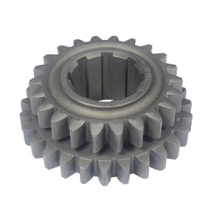
1. Cylindrical Gear Machining
Rough Machining Stage (e.g., Blank Turning)
Outer Diameter: Clamped using a three-jaw self-centering chuck or four-jaw independent chuck to ensure concentricity with the machine spindle.
End Face: Positioned via a center or end face presser plate to control axial dimensions.
Positioning Datum: Outer diameter and end face.
Purpose: Provide a stable blank datum for subsequent processes and reduce clamping deformation.
Finishing Stage (e.g., Hobbing, Shaping)
Inner Bore: Positioned using a mandrel (e.g., tapered mandrel or expansion mandrel) to ensure concentricity.
End Face: Restricted axially via an end face stop ring or presser plate.
Auxiliary Datum: For large-module gears, a drive pin (e.g., keyway) may be added to transmit torque.
Positioning Datum: Inner bore and end face ("one face and two pins" positioning).
Advantages: The high-precision inner bore (typically IT6–IT7) serves as the datum, significantly improving tooth profile accuracy; end face positioning controls axial dimensions, avoiding tooth depth errors.
High-Precision Machining (e.g., Gear Grinding, Honing)
Gear Grinding: Positioned using the machined inner bore and end face with a high-precision mandrel (e.g., hydraulic expansion mandrel) to minimize clamping deformation.
Honing: The tooth flanks themselves serve as the datum, with the honing wheel correcting tooth profile errors through meshing.
Positioning Datum:
Key Point: The fit clearance between the mandrel and inner bore (typically H7/g6) must be controlled to prevent vibration.
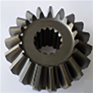
2. Bevel Gear Machining
Positioning Datum: Outer cone and end face.
Outer Cone: Positioned using a dedicated tapered mandrel or copy positioning to ensure alignment between the back cone and machine spindle.
End Face: Restricted axially via an end face presser plate to control the axial position of the bevel gear.
Adjustment Method: The back cone angle is adjusted through trial cutting to ensure the tooth contact pattern meets design requirements.
3. Worm Gear and Worm Machining
Worm Gear Machining:
Positioning Datum: Inner bore and end face, similar to cylindrical gears, but with additional radial positioning for the worm gear ring (e.g., locating pins).
Worm Machining:
Positioning Datum: Outer diameter and centers at both ends, clamped using two centers to ensure concentricity with the machine spindle.
III. Error Analysis of Positioning Datum
Datum Misalignment Error
Example: If the design datum is the gear's pitch circle, but the inner bore is used as the positioning datum during machining, concentricity errors between the inner bore and pitch circle will propagate to the tooth flanks.
Control Method: Improve inner bore machining accuracy (e.g., IT6) or adopt a "mutual datum" process to reduce errors.
Datum Displacement Error
Cause: Clearance between the positioning element (e.g., mandrel) and the workpiece's positioning surface leads to positional shifts.
Control Method:
Eliminate clearance using interference fits (e.g., hydraulic expansion mandrels).
Add auxiliary positioning surfaces (e.g., end face stop rings) to restrict degrees of freedom.
Clamping Deformation Error
Cause: Clamping forces from chucks or presser plates deform the gear blank.
Control Method:
Optimize clamping force distribution (e.g., using soft jaws).
For thin-walled gears, use dedicated expansion mandrels or vacuum chucks.